BESS EMS Integration and Commissioning Checklist for Indian Projects
A practical checklist for coordinating BMS, PCS, PPC, SCADA, meters, grid controls, cybersecurity and performance testing.
By Barat, Product Development Head, Urja Matters · Battery Energy Storage · 15 minute read · Reviewed 2026-09-10
Why commissioning is where BESS projects are won or lost
A battery container can pass factory testing and still fail at the point of interconnection. BMS data, PCS control, PPC logic, plant SCADA, protection, meters, communications, weather systems, contracts and operator workflows must behave consistently under normal, abnormal and recovery conditions.
SECI’s 600 MW/1,200 MWh BESS specification identifies racks/BMS, bidirectional PCS, auxiliaries, data acquisition, communications, EMS, plant SCADA integration, dispatchable energy, efficiency, availability and joint commissioning. For eligible SRAS participation, Grid-India’s published procedure covers bi-directional communications, telemetry, metering, activation, assessment, cybersecurity, open/closed-loop testing and settlement. Neither is a universal standard: adapt this checklist to the RfS, contract, grid code, connection agreement and authorities.
Principle: test the chain, not the boxes
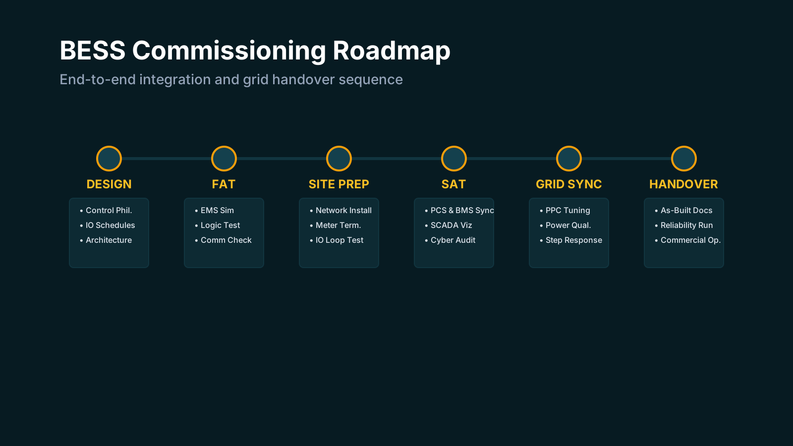
Progress from document control and simulation to subsystem tests, integrated FAT, site installation, SAT, grid synchronisation, performance demonstration and handover. Every test states precondition, initiating signal, expected response, measurement point, tolerance, responsible party, retained evidence and recovery/rollback method. If the result has no defined measurement point, the test is incomplete.
Phase 1 — Contract, design and responsibility readiness
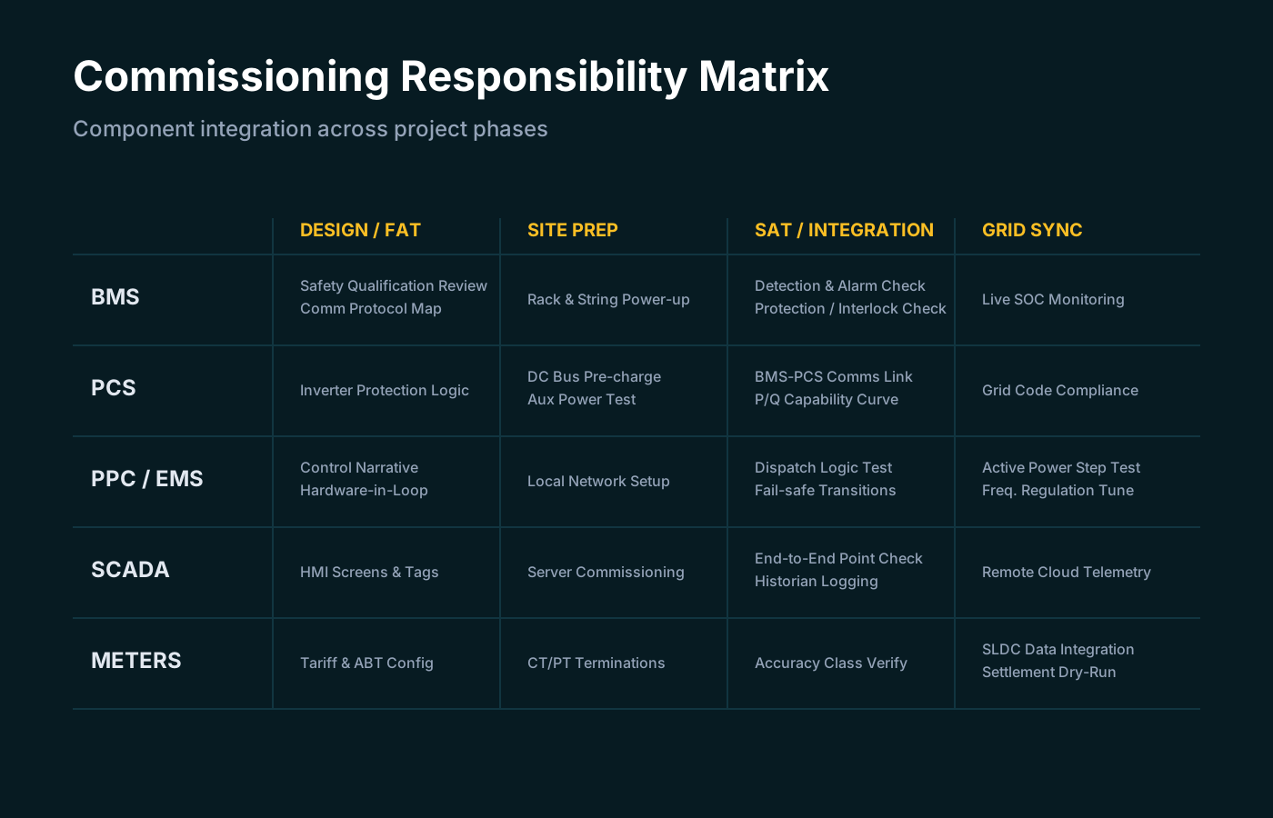
Close the matrix identifying owners for BMS, PCS, PPC, EMS, SCADA, revenue meter, protection, communications, cybersecurity, auxiliaries, fire systems, transformer, substation and grid interface.
| Design gate | Required evidence |
| Functional architecture | Approved single-line, control architecture and data-flow diagrams |
| Interface register | Signal, source, destination, units, direction, update rate, quality and timestamp |
| Command hierarchy | Priority among local, EMS, PPC, SCADA, operator, emergency and protection |
| Measurement points | DC rack, PCS AC terminal, transformer, POI and revenue-meter definitions |
| Operating modes | Charge, discharge, idle, reserve, maintenance, emergency, comms-loss and restart |
| Limits | SOC/SOH, current, voltage, temperature, power, ramp, transformer, import/export and auxiliaries |
| Network/security | Zones, conduits, identities, remote support, logging, time, backup and patching |
| Test basis | Approved FAT, SAT, grid-sync and performance procedures |
Distinguish nameplate from usable/dispatchable energy: a tender may require DC capacity sufficient to deliver defined MWh at POI after losses and degradation.
Phase 2 — EMS software readiness
Freeze tested version and configuration baseline: scheduler, constraint engine, command arbiter, alarm model, historian, dashboards, reports, roles, protocol drivers and fail-safe settings. Verify that it can ingest BMS/PCS/PPC/SCADA/meter/weather/contract data; flag stale, invalid, out-of-range and conflicting signals; calculate available power and dispatchable energy; create, revise and archive schedules; allocate SOC across obligations; send feasible commands without bypassing safety; detect rejection/derating/comms loss; select fallback; and produce event, performance and settlement reports. Resolve protocol, timezone, unit and sign-convention differences before site work.
Phase 3 — Factory Acceptance Test (FAT)
Use representative emulators or hardware-in-the-loop for BMS, PCS, PPC, meter and grid signals.
| Test family | Acceptance evidence |
| Signal integrity | Correct units, scaling, quality and timestamps |
| SOC and energy | Floor, ceiling, unavailable energy and degradation/augmentation response |
| Power commands | MW/MVAr/power-factor/ramp translation and bounded output |
| Schedule | Charge, discharge, hold, reserve and revised schedule within tolerance |
| Priority | Local, PPC, EMS, SCADA, emergency and protection behaviour |
| Fault handling | Alarms, trips, invalid/stale points and comms loss trigger defined actions |
| Recovery | Restart, resynchronisation, time recovery and dispatchable re-entry |
| Reporting | Events, alarms, schedules, actuals, deviations and operator actions export |
| Security | Roles, remote access, audit logs, password/certificate and network rules |
Include open- and closed-loop tests and response calculations where an ancillary procedure applies.
Phase 4 — Site installation and cold commissioning
Before energisation verify equipment identification, terminations, polarity, earthing, insulation, protection, auxiliaries, HVAC, fire detection/suppression, communications, network segregation, time synchronisation and physical safety. Compare the installed point list with the approved register. Confirm revenue meter, CT/PT circuits, PCS meters, BMS measurements and SCADA values are not assumed interchangeable.
Retain as-built drawings; cable and termination records; insulation/continuity; protection/interlock settings; network tests; firmware/configuration versions; cybersecurity hardening; calibration certificates; emergency response procedure; and red-line changes.
Phase 5 — Hot commissioning and subsystem tests
Energise auxiliaries, controls/communications, PCS and battery strings/racks using the approved method. Confirm BMS health before charge/discharge. Demonstrate BMS protection, thermal/auxiliary response, contactor/pre-charge, PCS start/stop/charge/discharge, active/reactive response, ramp and power-factor, PPC aggregation and POI behaviour, SCADA alarms/commands/trends/historian, meters/time and emergency stop. A local HMI “run” is not completion: verify the value at the correct interface.
Phase 6 — Integrated SAT and end-to-end tests
| Scenario | What to prove |
| Scheduled charge/discharge | Schedule follows without limits violation; metered POI delivery matches command |
| Renewable surplus/shortfall | Charge/discharge or reserve follows contract, export and SOC policy |
| Reactive request/ramp | POI response and required ramp without oscillation or conflict |
| Low SOC | Future obligations protected; infeasible request rejected |
| BMS derating/PCS trip | Energy/power recalculated, block isolated, plan and recovery controlled |
| Telemetry loss | Defined fallback, alarm, local control and recovery |
| Meter mismatch | Discrepancy flagged; settlement data never silently overwritten |
| Emergency stop | Safe state and authorised restoration |
Phase 7 — Grid synchronisation and performance
Plan jointly with BESS supplier, AC contractor, EPC, utility, system operator and EMS provider. Define authorised energisation, witnesses, exchanged signals and acceptance-record owner. Demonstrate contract-defined dispatchable energy, round-trip efficiency, availability, response, ramp, active/reactive power, power factor, auxiliaries, communications and schedule adherence. Make the measurement point explicit; do not replace contract criteria with “battery passed.”
Phase 8 — Handover and operations readiness
Handover final as-builts and configuration backups, software/firmware inventory, points/protocols, alarm/event dictionary, operating and emergency procedures, training and competency sign-off, cybersecurity/remote support, maintenance/calibration, warranty and guarantees, spares, escalation contacts and open-defect owners/dates. The historian must reconstruct schedule, actual output, SOC, limits, trips, curtailment, deviation and settlement value—not merely hold raw points.
Common gaps and conclusion
Recurring gaps include incomplete registers, inconsistent signs, meters treated as afterthoughts, unclear time zones, fighting local/remote controls, unknown validity of BMS values, late cybersecurity, and no owner for communications recovery. Another is testing at PCS while reporting POI performance without transformers, cables and auxiliaries. Every result needs an explicit measurement point.
An Indian BESS EMS commissioning checklist is a project-control document, not a software to-do list. Connect requirements to points, commands, measurements, tolerances, evidence and responsibility. Proving the chain from schedule to meter, BMS limit to fallback, and operator command to settlement report makes the project easier to finance, operate and scale.
References
- SECI, BESS tenders and technical specifications
- CERC, ancillary-services regulations and current amendments
- CERC, current regulations
For dispatch logic, see BESS dispatch scheduling in India; for control ownership, see BESS EMS vs BMS, PCS, PPC and SCADA.