BESS EMS vs BMS, PCS, PPC and SCADA: A Practical Guide for India
Compare BMS, PCS, PPC, SCADA and EMS roles in Indian BESS projects, with clear interfaces, safety boundaries and operating evidence.
By Barat, Product Development Head, Urja Matters · Battery Energy Storage · 14 minute read · Reviewed 2026-09-10

The five systems answer different questions
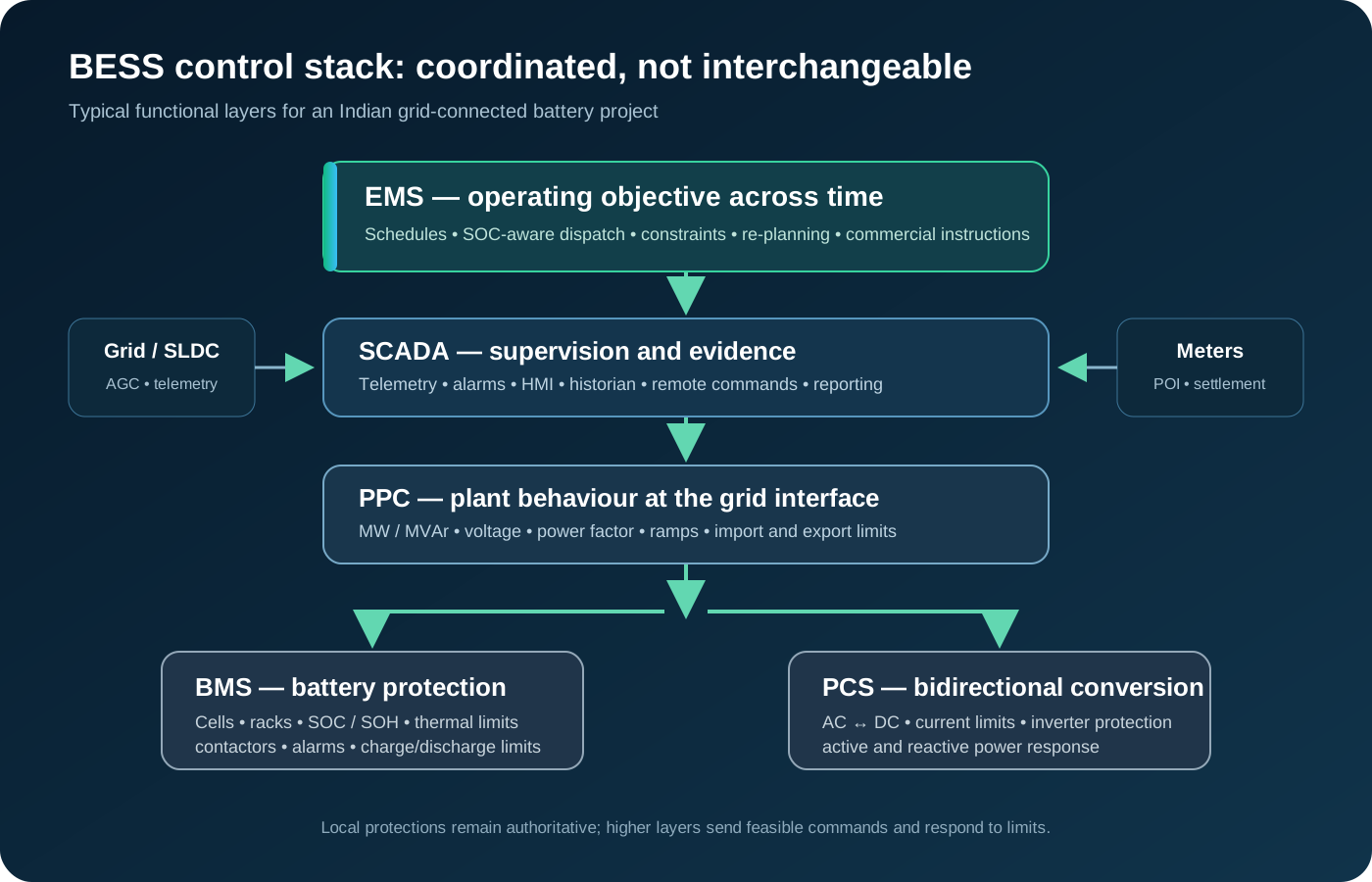
A battery energy storage system is not controlled by one universal software layer. The battery management system (BMS) protects and monitors cells and racks. The power conversion system (PCS) converts between DC battery power and AC power. The plant power controller (PPC) coordinates the site at the point of interconnection. SCADA provides supervisory visibility and operational control. The energy management system (EMS) turns contracts, forecasts and operating constraints into schedules and bounded objectives.
These boundaries matter in India because a project may need to satisfy a procurer, DISCOM, SLDC, RLDC or NLDC while also preserving battery warranty limits and electrical protection. Calling every layer an “EMS” hides ownership, creates conflicting commands and makes acceptance testing difficult.
BMS: battery health and protection
The BMS measures cell and module voltage, temperature, current, state of charge (SOC), state of health (SOH) and alarms. It balances cells where supported, controls contactors, calculates permitted charge and discharge limits, and trips or inhibits operation when the battery leaves its safe envelope. The BMS may also expose rack availability, insulation status and thermal-runaway indicators.
The BMS does not decide whether the project should arbitrage, reserve energy for an evening block or follow a grid instruction. It supplies the safe operating envelope to the control layers above it. A valid command from an EMS or PPC must still be rejected or limited when the BMS reports insufficient power, energy, temperature headroom or availability.
PCS: electrical conversion
The PCS controls the bidirectional conversion between battery DC and site AC. Its responsibilities commonly include current, voltage, active-power, reactive-power and power-factor control, as well as local trips, ramp limits and grid-support functions available in the equipment. The PCS reports actual output and limits to the plant controls.
The PCS is not the project scheduler. A PCS can execute a feasible setpoint, but it normally does not own the commercial obligation, forecast horizon, SOC reservation policy or settlement record. Its interface should document signs, units, resolution, ramp behaviour, command acknowledgement and the response when the BMS or grid protection constrains output.
PPC: site-level coordination
The PPC aggregates PCS units and coordinates the site at the point of interconnection. It can apply import and export limits, ramp rates, reactive-power or power-factor targets, plant availability and grid-code responses. It is often the final site control layer before the connection point and therefore needs accurate meters, time synchronisation and clear command priority.
An EMS may send a schedule or target to the PPC, while the PPC turns that target into coordinated equipment commands. The exact split depends on the project design. The contract and acceptance plan should state whether a limit is enforced by the EMS, PPC, PCS or more than one layer, and which system is authoritative when they disagree.
SCADA: visibility and supervised operation
Plant SCADA collects telemetry, alarms and statuses and provides operator displays, trends, historian functions and approved supervisory commands. It is the operational window into the plant and may interface with the utility or system operator. SCADA should not silently rewrite an EMS schedule or bypass BMS, PCS, PPC or protection limits.
Treat the historian and the control path as separate design concerns. A value shown on an HMI is not necessarily a revenue-meter value, and an operator command is not evidence of delivery at the point of interconnection. Retain source, timestamp, quality, command, acknowledgement, limiting reason and measured result for important events.
EMS: optimisation and energy coordination
The EMS coordinates the project objective across time. It can ingest forecasts, market or contract instructions, SOC, equipment availability, tariffs, schedules, reserve requirements and measured delivery. It may create a feasible schedule, allocate energy across services, detect deviation risk and produce operational or settlement reports.
The EMS must not replace certified protection or invent capacity that the BMS and PCS cannot deliver. A sound design sends a bounded schedule or target to local controls, receives the accepted setpoint and records any limiting reason. Site controls should retain a safe local mode if cloud or wide-area communications fail. The BESS architecture guide describes this cloud-edge separation.
A practical command hierarchy
Document one command hierarchy before integrating equipment:
- protection trips and emergency stops have authority over all supervisory requests;
- the BMS defines battery safety and permitted operating limits;
- the PCS enforces conversion and equipment limits;
- the PPC enforces site and point-of-interconnection limits;
- SCADA provides approved supervision and operator visibility;
- the EMS manages schedules, objectives, forecasts and commercial evidence.
This is a useful default, not a substitute for a project-specific control narrative. Manual, scheduled, market, ancillary-service and grid-operator commands also need an explicit priority. Every command should carry source identity, issue time, validity window, requested value, accepted value and rejection or limiting reason.
Interfaces and acceptance evidence
An interface register should identify each signal’s source, destination, direction, units, scaling, quality flag, timestamp, update rate, timeout and fallback. Include BMS SOC and limits, PCS availability and actual power, PPC setpoints, SCADA alarms, revenue-meter values, weather and forecast inputs, and any SLDC, RLDC or NLDC exchange.
Factory and site acceptance tests should demonstrate normal charge and discharge, SOC ceilings and floors, ramp limits, partial PCS availability, stale telemetry, conflicting commands, communications loss, meter mismatch, emergency stop and recovery. Test at the commercial measurement point, not only at a container or PCS terminal. The BESS dispatch optimisation guide explains how these constraints become an executable plan.
What to ask a supplier
Before approving an architecture, ask:
- Which layer owns each limit and what happens when two layers disagree?
- Can the plant continue safely during EMS, SCADA, PPC or wide-area communications loss?
- Are SOC, SOH, dispatchable energy and availability defined at the same measurement boundary as the contract?
- Can operators reproduce a command, acknowledgement, limit and measured response from retained records?
- Are roles, network zones, remote access, certificates, backups and change control documented?
- Can the design accommodate current CEA, CERC, Grid-India, utility and project-specific requirements without hard-coding one pilot?
The answer should be an interface and evidence package, not only a block diagram. For tender language, use the BESS procurement checklist.
References
- Central Electricity Authority, regulations: grid connectivity, safety, metering and communication.
- Central Electricity Regulatory Commission, Indian Electricity Grid Code Regulations, 2023.
- Grid Controller of India, system operation procedures and reports.
- Ministry of Power, electricity rules and energy resources.